
 |
Search | FAQ | US Titles | UK Titles | Memories | VaporWare | Digest | |||||||
| GuestBook | Classified | Chat | Products | Featured | Technical | Museum | ||||||||
| Downloads | Production | Fanfares | Music | Misc | Related | Contact | ||||||||
| Installing Clear Tops on J/K CED Players | ||||||||||||||
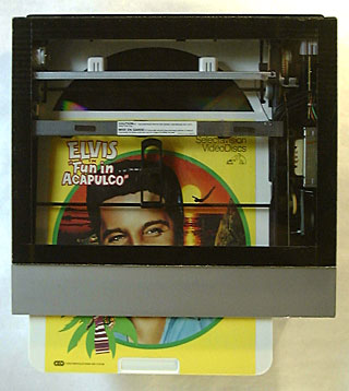 This page provides instructions for installing see-through covers on J/K CED players by cutting a rectangular hole in the existing cover and closing it with a piece of transparent acrylic plastic. The procedure is designed so that a few simple hand tools can accomplish this task, while still maintaining a professional appearance in the finished product. The purpose of having a clear top is so onlookers can observe the caddy extraction mechanism on these players, as well as other operations, like the movement of the disc between the load and play positions, and the playback of the disc itself. RCA made a few clear-top SFT100 players in 1980 for this very purpose, but I've never seen or heard of factory-manufactured J/K models, which being motorized, have the coolest mechanisms of all CED players. The only retail player model with a see-through opening was the Toshiba VP100 which had just a tiny little window useful only to verify that a disc was loaded and spinning.
Although this procedure will work on all J/K CED players, I selected the SJT300 model, mainly because I wanted a stereo player with factory remote control. This plain black cover of this model also has a couple of other advantages in that there is no lacquer coating to get damaged, and after the hole is cut, the natural black color of the remaining plastic provides a nice frame around the somewhat gray interior of the player. This model also has simulated woodgrain sides on the cover which give the finished player a semi-retro appearance.
Here are the items you need to complete the installation of a clear cover:
The drill bit and pin vise can be obtained at a local hardware store. The transparent mounting tape is a specialty item that craft stores like Michaels will have in stock. Look in your Yellow Pages under "Plastics" to find plastic companies that can provide the clear acrylic as well as the Plasticutter tool. Clear acrylic will be sold under a variety of trade names including Acrylite, Chemcast, Lucite, and Plexiglas. When purchasing the piece required for this clear cover, you can either have the plastic company cut it to the exact dimensions of 16.75 x 12.75 inches, or look in their bargain bin or bargain basement for a larger piece, which you can score to the correct dimensions with the Plasticutter tool. Plastic companies wind up with a lot of odd remnants and the chances of finding a surplus piece this small are pretty good. I found my piece in the bargain basement at the local Multi-Craft Plastics store. I happened to find a piece with a scratch-resistant coating on one side, which is useful to have facing outward on the CED player to prevent scratches as people touch the top and you periodically have to clean it. If you buy the plastic custom-cut, you can specify this scratch-resistant coating (unless you plan to flame polish the edge, see below). Acrylic sheet comes with protective paper on both sides that should not be peeled off until just before the cover is installed on the player. When looking through the bargain remnants, test the integrity of this paper by peeling a corner back a little bit and then pressing it back down. If the paper is permanently stuck to the plastic, you unfortunately found an extremely old remnant, or one that has been exposed to ultraviolet radiation.
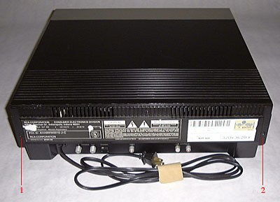 (1) Begin the clear top installation by removing the cover from the CED player. There are two Philips screws at the rear of the player cover. Remove these screws and lift up on the rear of the cover to remove it.
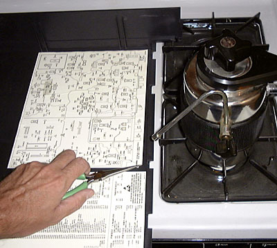 (2) The inside of the cover will probably have three labels pertaining to the technical operation of the CED player. I first attempted to remove these intact with a jet of steam from a stove-top expresso/cappuccino maker, the same method used to expose the hidden label on some CED caddies. But I soon found these large labels would not come off easily and resorted to a more expedient method to remove them. This involved completely saturating the label with Goo Gone, letting it soak for a while, and then removing the label by a combination of peeling and scraping. Note that you can simply leave these labels in place if you like. The Plasticutter tool will cut right through them when the opening is made in the cover.
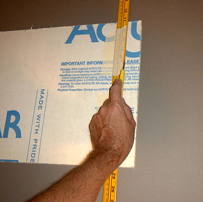 (3) If you got an oversize piece of acrylic sheet, gain familiarity with the Plasticutter tool by first scoring the acrylic to the proper dimensions before working on the player cover. In this picture I'm removing a little over an inch of plastic from the edge of the sheet to achieve the required 16.75 inch width. This involves taping the yardstick where the groove needs to be cut and using its edge as a guide for the Plasticutter tool. The tool is drawn towards the user with the cutting hook pressing down against the acrylic sheet. The first pull will cut through the protective paper and make a straight groove in the underlying acrylic surface. The tool is repeatedly used in this fashion with each pull cutting off another thin ribbon of material and making the groove a little deeper. After a few pulls the yardstick can be removed, as the tool has a natural tendency to ride in the ever-deeper groove. Pull the tool so it completely jumps off the material, and periodically rotate the sheet 180 degrees, so you are pulling in the opposite direction. This will ensure a deep groove at both edges of the sheet. When the groove has a depth of about 1/32 inch, you're ready for the next step of breaking it off.
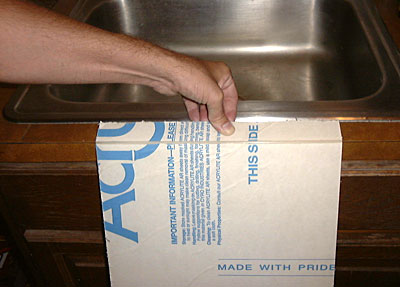 (4) Take the scored acrylic sheet to a kitchen counter or table that has a sharp right-angle edge. The sheet can be cleanly broken along the groove by a single press against this right-angle edge. Hold the acrylic sheet with one hand on the portion of the sheet to be discarded and the other hand on the portion to be retained, with the cut groove facing away from the right-angle edge. Carefully line the cut groove up with the right-angle edge and then give a press with both hands. As shown in the picture, the sheet will cleanly break along the groove. The protective paper on the opposite side of where the groove was cut can then be trimmed with a scissors or the Plasticutter tool to separate the two pieces.
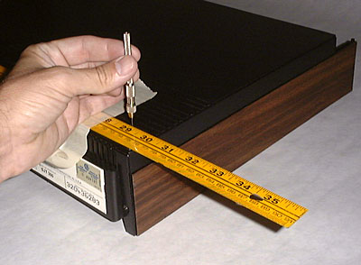 (5) This step involves hand drilling four 1/32-inch holes in the player cover that will correspond to the four corners of the rectangular opening being cut out. There are several reasons for drilling these four holes before using the Plasticutter tool. The first is to ensure you indeed do have a precise rectangular opening before causing any inadvertent scoring damage to the cover. Another reason is that the holes provide a start and stop detent for each stroke of the Plasticutter tool. And the holes provide precise reference points on both the outside and inside of the player cover. For the smoothest possible opening, the cover should be scored on both sides.
I decided to leave one-inch edges on my cover, which worked out well, as the yardstick is one inch wide, and the mounting tape to be put along the edges is also exactly one inch wide. In this picture, the yardstick is taped down in precise alignment with the back of the cover with the 30-inch mark aligned with the adjacent side. By drilling the hole at the 29-inch mark, a one inch border is achieved. Repeating this process at the other three corners results in a precise rectangle with even borders on all four sides. It might seem odd to drill a hole by hand, but it only took about 15 seconds of rotating the pin vise to punch through. So the hole could even be drilled by something as improvised as holding the drill bit with a slip-joint pliers. Of course, the hole could instantly be drilled with a power drill, but the goal here is to install the clear cover without having to resort to any power tools.
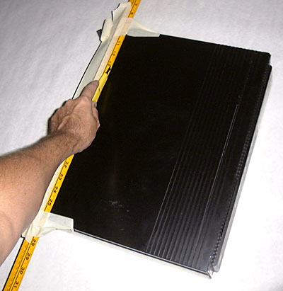 (6) The player cover is scored in much the same way the acrylic sheet was scored in step (3), except in this case the scoring is continued until the cover is completely cut through. The polystyrene plastic of the cover is softer than the acrylic plastic of the clear sheet, so the scoring process is easier. Begin the scoring with the front of the cover, as that will be the weakest area once the hole is completely cut out. In this picture, the yardstick is taped down immediately adjacent to the two drilled holes on the front side of the cover, and the Plasticutter tool is being pulled between the two holes using the yardstick as a guide. Be careful when approaching the stop hole, as it's possible to inadvertently pull the tool past the hole. And note that the ruler is taped down outside the hole being cut rather than inside. That way, if the cutter accidentally slips during those critical initial cuts, it will only damage the portion of the cover being discarded. If you feel confident with the scoring process, the ruler can be removed after the groove is cut to a certain depth. Although most scoring should be done from the outside of the cover, a little scoring should also be done from the inside, to cut through those labels that may still be in place, and to provide a slightly cleaner opening.
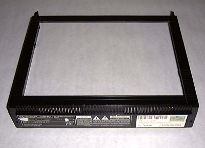 (7) Here is the cover with the hole completely cut out. Note how little support there is across the front of the cover, so handle it carefully until the clear acrylic sheet is safely in place on top of the cover.
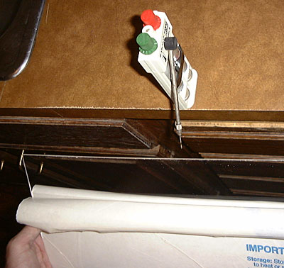 (8) This step is completely optional, as it only makes a minor appearance improvement in the finished product. If you have seen store fixtures made out of thick acrylic sheet, you may have noticed that the edges are as transparent as the face of the sheet. The edges didn't look like that immediately after being cut, but were probably made to look that way by buff polishing. This involves sanding the edge down with fine sandpaper, and then buffing the edge with buffing compound and a cloth wheel to a transparent finish. Another way to accomplish this is by flame polishing where the edge is quickly drawn across a hot flame, which liquefies the plastic and gives it a transparent finish within seconds as the plastic rehardens. The Microflame Torch shown in the picture mixes nitrous oxide with butane to yield a very hot flame, which produces the best results when flame polishing. But the process still works to some degree with ordinary propane or butane torches. Acrylic manufacturers do not recommend using flame polishing on sheet with scratch resistant coating because the flame overlapping the edge may produce misting in the clear plastic surface. But because the Microflame Torch produces such a tiny flame, this did not happen in my case. Flame polishing can also be used to make the dull black edges of the cut out hole in the player cover more shiny. Practice this technique on the discarded rectangle from the cover, and have water nearby, as it's possible to set the plastic on fire if the torch is drawn over the edge too slowly. Polishing the edge doesn't make for much of an appearance change with this clear cover project, since the acrylic sheet is only 1/8-inch thick.
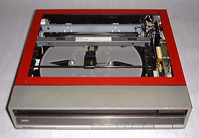 (9) Here is the cover back on the player with the transparent mounting tape, and its red backing, surrounding the opening. Line the mounting tape up carefully, as it's very difficult to pull off once pressed into place. You will need almost all of the 60-inch roll to surround the opening, so don't waste any of the mounting tape. The clear plastic sheet should be lowered into place with the cover back on the player as shown, as this provides the most stability. You only have one chance to lower the clear acrylic into place so practice how you're going to lower it while the red backing on the mounting tape is still in place. Just before installation, remove the protective backing from the inside of the acrylic sheet, but leave it on the outside. I recommend lining up the sheet along the front edge first, and then lower the clear cover into place as if it were hinged along the front edge.
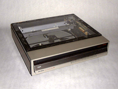 (10) Here is the player with the transparent cover in place. After the clear sheet is installed you should remove the cover from the player and lay it upside down on a flat surface. Then press around the one-inch border of the cover to seat the mounting tape even more firmly. At that point the protective paper on the outside of the cover can be removed. This picture was taken right after the protective paper was peeled off, and you may be able to see spots where the mounting tape is not consistently adhering to the plastic surface. These were eliminated by removing the cover and applying squeezing pressure from both sides simultaneously. A few of the more obstinate spots were squeezed out using a 4-inch C-Clamp with a piece of protective cloth under the jaw to protect the transparent surface. Once these are squeezed out, and the cover is installed back on the player, the basic clear top project is complete.
I wanted to not only install a clear top on my player, but also provide subtle, continuous illumination for the interior of the player. This was accomplished by installing some LED circuit boards designed to run on 120 Volts AC. I'm going to necessarily be somewhat vague about how this was done because you should not work with this type of circuitry unless you know how to properly wire AC circuits. Without prior experience, attempting to do this presents both a shock and a fire hazard. If you want to illuminate your player, but lack experience working with AC electricity, I recommend using Cool Neon electroluminescent wire. Their Ready To Glow products come preassembled, and provide a variety of ways to illuminate the CED player.
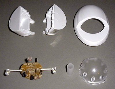 (Optional) To illuminate my player, I installed six high-intensity white LED's hidden from view under the guide rail bracket that extends across the player near the center of the turntable. These light emitting diodes were obtained from a $10 three-pack of LED night lights purchased at Costco. Each of these was disassembled as shown in this picture to get the small circuit board with two LED's on each board. The lamps are each mounted at the end of a one inch wire, which facilitates pointing them in different directions inside the player. The board also has a CdS photoresistor that turns the LED's on only when the ambient light level is low. This photocell can easily be defeated by covering it with a piece of black tape, which will leave the LED's on continuously. With a lifespan of about 10 years in constant use, these LED's won't burn out anytime soon.
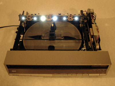 (Optional) This picture shows the guide rail bracket lifted up and reversed to show the LED boards hidden underneath. The boards are glued to the metal rail with non-conductive silicon adhesive. They are wired directly to the 120 Volt AC player input, so the lamps are powered-up whenever the player's power cord is plugged into an AC outlet.
All J/K players except the 400 models have a repeat mode entered by holding down the PAUSE/PLAY button while turning the player on. In this mode the entire disc side is played, and the player mechanism moves to the unload position. After 15 seconds, the mechanism moves back into the play position and this process repeats indefinitely until the player is turned off. By loading a disc into the player with an empty side up, the load/unload mechanism will go through a complete cycle in about 40 seconds, as the mechanism microcomputer reads the REJECT band a few seconds after the pickup arm moves to the PLAY position. This technique can be used for a short-term automatic demonstration of how the player mechanism works. I set my player up for this purpose by installing a replacement function motor, but I used a 15 Ohm, 1 Watt resistor rather than the 10 Ohm resistor supplied with the motor. This reduced the current flow through the function motor a bit, slowing the mechanism down and putting less stress on it. On most two-disc titles, Side 2 of Disc 2 is empty and marked with the code 7647699999. The 400 series players do have a repeat mode, but it only moves the pickup arm to repeat a programmed segment rather than cycling the load/unload mechanism.